FIR Filters by Frequency Sampling, Transition Samples 2
Cuthbert Nyack
In this applet, the length of the filter is set by scrollbar 63. Scrollbar 30 sets the type of filter ie LP, HP, BP and BS. The number of transition samples is set by
scrollbar 33 and the numerical values of the transition samples is shown on the right.
The numerical value of each transition sample can be set to 8 decimal places eg the first transition sample is value of scrollbar(0) + (1/100) value of scrollbar(1) +
(1/10000) value of scrollbar(2) + (1/1000000) value of scrollbar(3) + (1/100000000) value of scrollbar(4). The second transition sample is set by scrollbars(5 - 9) etc.
Here the samples are plotted on a log scale in dB and superimposed on the frequency response so it is easier to see the effect of the samples on the frequency response.
For LP the number of samples in the pass band is set by n1(31).
For HP the number of samples in the stop band is set by n1(31).
For BP the number of samples in the first stop band is set by n1(31) and the number
of samples in the pass band is set by n2(32).
For BS the number of samples in the first pass band is set by n1(31) and the number of samples in the stop band is set by n2(32).
dBS(58) sets the value of the samples in the stop band, dB(57) sets the dark red
reference line and dBS(56) sets the dB/div.
As already mentioned good values of transition samples can only be
obtained numerically but acceptable values may be obtained manually. The
main consideration in adjusting the transition samples is the compromise between
transition bandwidth and stop band attenuation. It is also necessary to minimise
any discontinuity in the response or its derivatives. Differentiable functions such as
sinusoids or the gaussian distribution may be used to obtain a first approximation
for the transition samples.
The difficulty associated with finding good stop band attenuations can be visualised by considering the case of 2 transition samples. As the samples are varied, one is moving over a surface which has several 'local' minima as well as a lowest minimum. As this is often described in books, one might be tempted to adopt the approach of varying each sample individually and locating a minimum each time. Unfortunately with this approach, it is easy to get stuck in the same local minimum with the same transition sample values.
A better approach is to start with smaller than required sample values. When it becomes apparent that one is stuck in a local minimum, then one should go back to the largest sample and increase it past the value which produces a minimum, it may mean going to a value where the stop band frequency response begins to look equiripple. This is uncomfortable at first because it appears that one is heading in the wrong direction. However this is necessary to breakout of the local minimum. From the largest sample one then moves on to the smaller samples. In doing this one must remain aware of the fact that the transition samples are bounded by one sample with a fixed value of 1 and another with a fixed value of 0.
With this approach it is possible to get stop band attenuations of ~ 65 - 70dB for 2 transition samples, 80 to 85dB for 3 transition samples and 95 - 100dB for 4 transition samples by interactive adjustment of the samples.
Some books mention tables of transition sample values. With the exception of those for 5 transition samples quoted from Ifeachor et al below, I have not seen such tables. However if such tables are available, they can be entered in the applet and used as starting points
for fine adjustments for the particular filter required.
The net effect of the transition samples is similar to that of windows. They
both sacrifice transition bandwidth for stop band attenuation. However windows
operate directly on the impulse response while transition samples directly affect
the frequency response.
The final result is the impulse response and this is shown on the third line as I(n) when n is set by scrollbar 62. The white and blue frequency markers controlled by scrollbars 60 and 61 can be used to find the gain at any frequency.
Images below show variation of stop band attenuation with number of transition
samples.
Cases for 2 to 4 are obtained by the interactive approach.
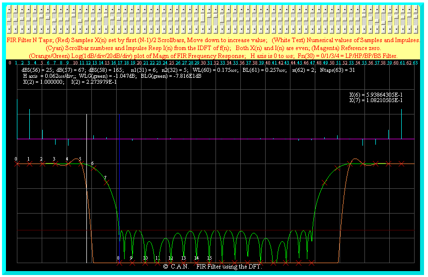
A case using interactive manipulation of 2 transition samples is shown below. The stop band attenuation is ~ 67dB.
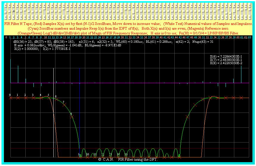
A case using 3 transition samples is shown below. The stop band attenuation is ~ 85dB.
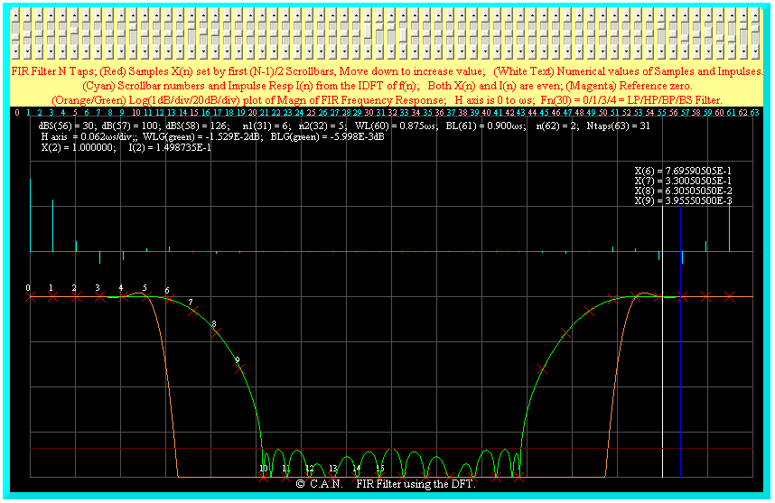
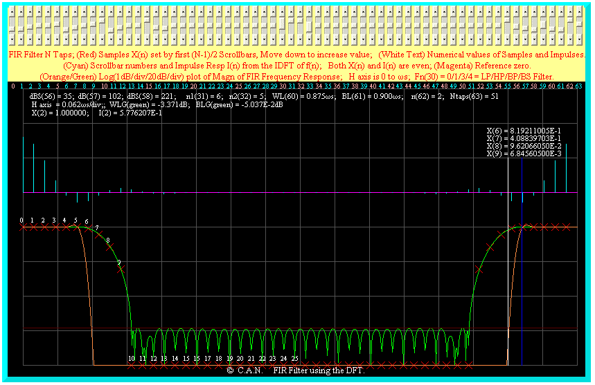
2 cases using 4 transition samples are shown below. The stop band attenuation is ~ 100dB and ~102dB. Using this interactive approach it is possible to get attenuations of
~ 100db consistently with 4 transition samples.
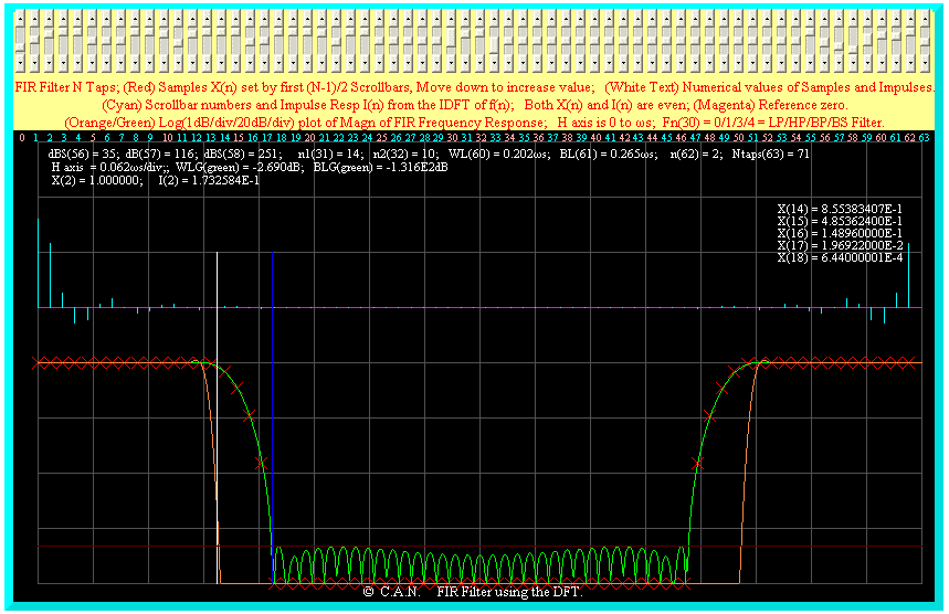
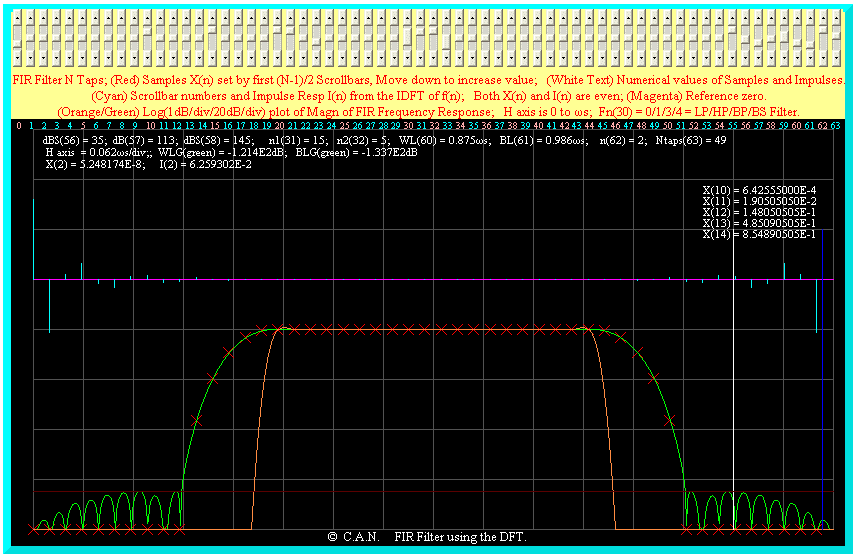
For 5 transition samples, it is better to start with published samples and adjust them.
The next 2 cases use the samples shown in Ifeachor et al. One of the
redeeming features of this approach is that a set of calculated values can be used
as a starting point for other cases with different filter lengths and
band edges.
The stop band attenuation is ~ 116dB.
 The stop band attenuation is ~ 113dB.
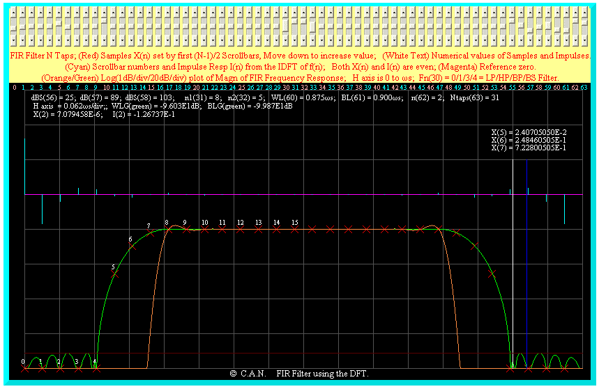
A high pass filter with 3 transition samples is shown below.
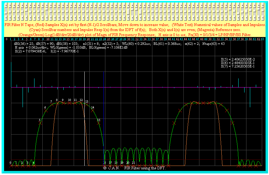
A band pass filter with 3 transition samples is shown below. This suggests different
samples may be required on each side of the pass band.
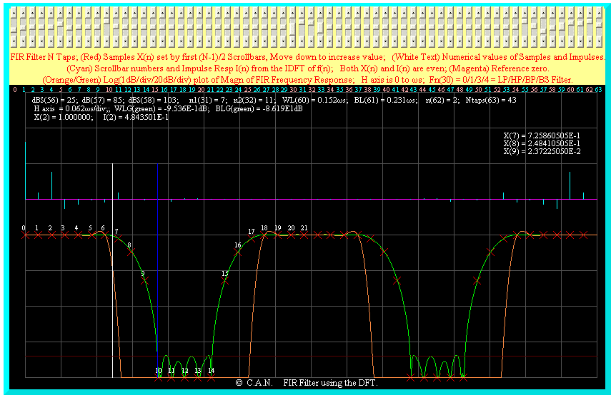
A band stop filter with 3 transition samples is shown below.
Return to main page
Return to page index
COPYRIGHT © 2008 Cuthbert Nyack.


